
Zone First Fix for VAV Box Not Cooling: Brighton Air's 50°F–60°F Test
Zone First Fix for VAV Box Not Cooling: Brighton Air’s 50°F–60°F Test
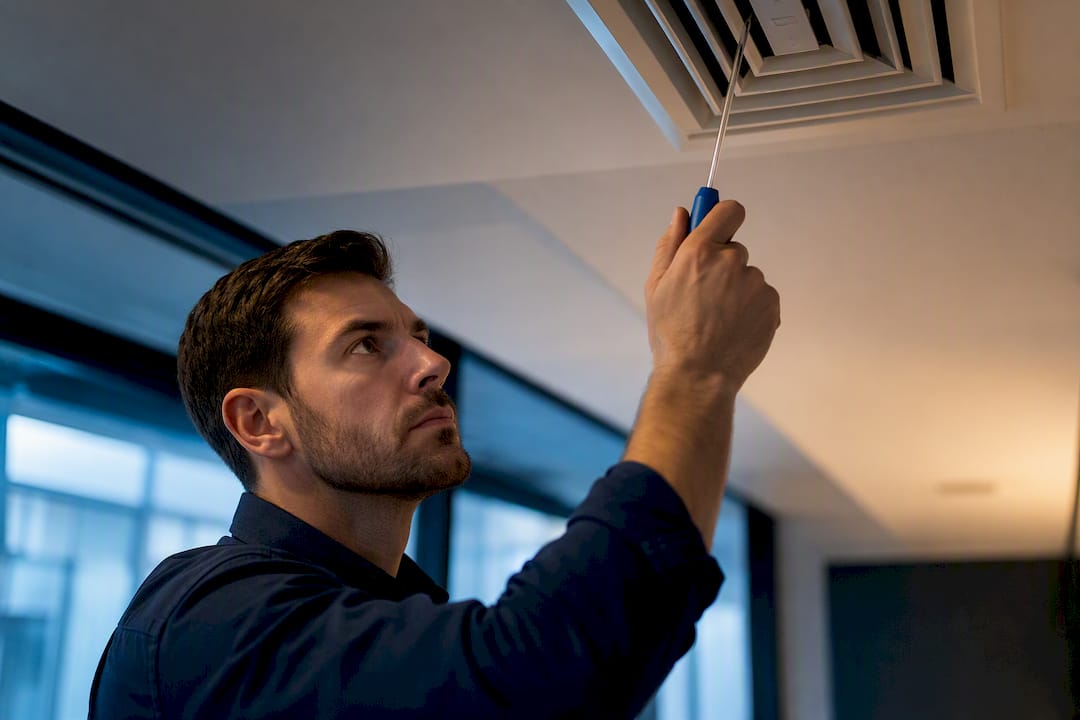
A VAV box that won’t cool almost always traces back to one of five culprits: a starved box not getting enough air from the AHU, a stuck or leaking reheat valve, a dead actuator or disconnected linkage, a fouled airflow pickup, or an AHU delivering supply air that’s too warm to begin with. Before you touch anything, confirm the BAS is actually calling for cooling, then measure supply-air temperature at the diffuser. That single reading tells you whether the fault lives at the terminal or upstream.
TL;DR:
- Most VAV boxes not cooling are caused by upstream issues like faulty airflow pickup tubes or supply air temperature that’s too warm, rather than the terminal itself.
- Confirming the BAS is calling for cooling and measuring diffuser air temperature is crucial to differentiate between upstream system faults and terminal problems.
- Inspect the zone sensor placement, airflow damper movement, and BAS trend data to identify whether the fault lies in control signals, sensors, or mechanical components.
- A diffuser temperature of 50°F to 60°F at maximum cooling indicates proper supply air; warmer air suggests upstream or reheat valve issues needing immediate attention.
- Repairs should focus on cleaning or replacing pickup tubing, fixing or replacing actuators, and addressing leaking reheat valves, with implementation guided by systematic diagnosis and documented BAS trends.
Table of Contents
- Diagnosing a VAV Box Not Cooling: Where to Start
- Zone-Level to Upstream: The Full Diagnostic Sequence
- Tools and BAS Readings You Need for an Accurate Diagnosis
- Fixing the Problem: Repairs You Can Do Right Now
- When to Stop Troubleshooting and Call a Specialist
- Preventive Maintenance That Keeps VAV Boxes Cooling
- Brighton Air Corp’s Perspective on Persistent Cooling Faults
- Ready to Book a VAV Diagnostic Visit?
- Sources
Diagnosing a VAV Box Not Cooling: Where to Start
Skip the guesswork and work through this list in order. Most terminal complaints resolve inside 15 minutes once you know what to check first.
- Confirm occupancy mode and the cooling call. Pull up the zone in the BAS and verify it’s in occupied mode with an active cooling request. A box sitting in unoccupied setback with a raised minimum flow will feel warm even when nothing is broken.
- Log the complaint precisely. Note the room number, time of day, and whether the complaint is constant or intermittent. Intermittent warmth often points to a schedule mismatch rather than a hardware fault.
- Cross-check the zone sensor. Hold an independent thermometer next to the wall sensor for two or three minutes. A sensor reading 3 to 4 degrees off from a handheld thermometer, or one mounted near a supply diffuser, doorway, or window, will trigger false satisfaction and stall the cooling call.
- Measure diffuser supply-air temperature at maximum cooling flow. Force the box to full cooling through the BAS and hold a thermometer at the diffuser face. You want 50°F to 60°F coming out, according to guidance from Price Industries. Anything warmer signals an upstream or reheat problem.
- Watch the damper move. Command the actuator open and closed while you observe the blade directly, or feel for the airflow change at the diffuser. No movement means a dead actuator, a snapped linkage, or a slipped shaft coupling.
- Inspect the airflow pickup tubing. Trace both tubes from the flow sensor to the pickup ports. Kinks, disconnections, or condensation blockage will feed the controller a false flow signal that either starves the box or maxes it out for no reason.
If steps one through three check out and the diffuser still runs warm, you’re past a quick fix. Move to the full diagnostic sequence below.
Zone-Level to Upstream: The Full Diagnostic Sequence
This is where you separate a bad sensor from a bad actuator from a bad AHU. Work through it in order. Each test either clears a component or points you to the next one.
Start with the zone sensor. Confirm it’s mounted away from supply diffusers, direct sunlight, exterior doors, and equipment that throws off heat, like a copier or server rack. A sensor reading within 1 degree of your handheld thermometer, taken at chest height in the middle of the room, passes. If it doesn’t, replace or relocate the sensor before doing anything else, since every downstream test depends on a trustworthy zone reading.
Pull the BAS trend and controller status next. Open the cooling PID loop and check the present value against the setpoint. A PID that’s pegged at 100% output for an extended period, with the box still not reaching setpoint, is what Johnson Controls documentation calls a saturated loop, and it usually means the box physically can’t deliver what the controller is asking for. Also check the occupied/unoccupied mode, the minimum and maximum flow setpoints, and any Starved Box alarm flag. A Starved Box flag specifically tells you the box can’t reach commanded flow even with the damper fully open, which shifts your suspicion toward duct static pressure or a central air supply issue rather than the terminal itself.
- Cooling PID present value stuck near 100% with no flow response: suspect a mechanical block, not a controls problem.
- Starved Box flag active: check duct static pressure and the AHU before you touch the terminal.
- Mode showing unoccupied during a complaint logged during business hours: check the schedule, not the hardware.
- Min/max flow setpoints that look unusually tight: verify against the original design documents before adjusting.
If the shaft moves but airflow at the diffuser doesn’t increase, the linkage between the actuator and the damper blade has likely slipped or broken. If the actuator doesn’t move at all, check for 24VAC power at the actuator terminals with a multimeter before condemning it. A powered actuator that still won’t move is dead; one with no power points you back to a transformer, fuse, or wiring fault.
Measure actual airflow, not just commanded flow. Use a differential pressure gauge or a hood-mounted anemometer at the diffuser to compare measured CFM against what the BAS thinks it’s delivering. A box that reports high commanded flow but delivers low measured flow, with the damper visibly wide open, is a starved box, meaning the terminal isn’t the problem; the central system is. A box that reports low commanded flow and delivers low measured flow, with a stuck or barely-moving damper, is a terminal-side mechanical fault.
Run the decisive test last: full cooling flow, diffuser temperature. According to PNNL’s operations and maintenance guidance, separating terminal faults from system-level faults is the core skill in VAV troubleshooting, and this test is how you do it in under two minutes. Command the box to maximum flow and hold a thermometer at the diffuser. Supply air landing in the 50°F to 60°F range with airflow still weak tells you the terminal itself is restricting flow. Supply air running warmer than 60°F, even with the damper fully open and flow measuring correctly, means the AHU discharge temperature is off, a reheat valve is leaking hot water into the cooling supply, or there’s duct leakage upstream pulling in warm return or plenum air.
Pro Tip: Don’t adjust the AHU supply-air setpoint to compensate for one warm zone. Raising central cooling temperature to fix a single starved box masks the real problem and makes every other zone on that air handler run warmer than it should.
Fan-powered VAV terminals complicate this sequence slightly. A series fan-powered box has an inline fan that runs continuously, so airflow at the diffuser won’t drop to zero even when the primary air damper is closed, which can mask a stuck damper if you’re only listening for airflow changes rather than watching the damper directly. Parallel fan-powered units draw from the plenum, so a plenum pressure problem can look identical to a primary-air problem unless you check both sources independently.
Tools and BAS Readings You Need for an Accurate Diagnosis
You can’t diagnose a VAV cooling fault by feel. Carry the right instruments and pull the right screens, or you’ll end up guessing.
Handheld tools:
- A contact thermometer for pickup tubing and coil surfaces, plus an infrared thermometer for quick diffuser and duct readings.
- A manometer or magnehelic gauge for duct static pressure and pickup tube differential.
- A pitot tube or vane anemometer for measuring actual airflow at the diffuser or inlet.
- A multimeter for checking actuator voltage, control signal, and continuity on suspect linkages.
- A small hand pump or vacuum tester for confirming the pickup tubing holds pressure without leaking.
BAS screens to pull before you touch anything:
- Cooling PID present value and setpoint, to check for a saturated loop.
- The nvoEwmaFlow or equivalent flow-error value, which flags a persistent mismatch between commanded and actual airflow.
- Starved Box status flag.
- Duct static pressure at the AHU and at the box inlet.
- Supply-air setpoint versus actual supply-air temperature.
- Actuator duty cycle or run-time, which can flag a motor working overtime against a bad linkage.
Diffuser supply-air temperature between 50°F and 60°F at max cooling flow is your pass/fail line for the AHU side of the equation, and it’s worth writing on the work order every time.
Screenshot the BAS trend before making any changes, and photograph the pickup tubing and actuator condition. EnergyStar’s building upgrade guidance recommends this kind of documentation specifically because it speeds up warranty claims and gives the next technician a real baseline instead of a verbal description.
Fixing the Problem: Repairs You Can Do Right Now
Once you’ve isolated the fault, most terminal-side repairs are straightforward. Work through the fix that matches what your diagnostic sequence turned up.
- Clear or replace fouled pickup tubing. If the tubes show kinks, moisture, or debris, cut out the bad section and re-route with new tubing rated for the pressure range. Recalibrate the flow sensor afterward. A pickup that reads clean but still delivers erratic flow signals may need full sensor replacement rather than just a tubing swap.
- Replace a dead or slipping actuator. Confirm 24VAC power and a valid control signal first with your multimeter. If both check out and the shaft still won’t turn, swap the actuator. While it’s off, inspect the linkage for wear at the pivot points and replace any stripped or bent hardware.
- Address a leaking or stuck reheat valve. A valve that won’t fully close will bleed hot water into the airstream even when the BAS calls for pure cooling. Test the valve stem for free movement, and check for a stuck actuator or a failed spring return. Bleed air-bound hydronic coils and confirm pump pressure and hot-water supply temperature before assuming the valve itself is the fault.
- Adjust BAS parameters only after confirming physical capacity. If measured airflow can legitimately reach a higher max cooling setpoint without triggering duct noise complaints, raising the Max Cooling Flow value can solve a chronically warm zone. Never raise this value as a workaround for a mechanical fault you haven’t fixed.
- Use temporary measures sparingly. A manual damper override or a slightly raised minimum flow can buy comfort for a day while parts are on order, but both carry a real energy cost and neither should stay in place past the repair visit.
Pro Tip: Always retest diffuser temperature and measured airflow after any repair, not just commanded flow on the BAS screen. A controller reporting success and a diffuser blowing warm air are two different facts, and only one of them matters to the person sitting in that office.
When to Stop Troubleshooting and Call a Specialist
Some faults are outside what a field check should attempt to fix, and pushing past that line creates real risk.
- Electrical actuator burnout or repeated fuse trips at the terminal transformer point to a wiring fault that needs a licensed technician, not another actuator swap.
- Hydronic coil issues involving air-bound piping, failed pumps, or contaminated glycol loops require system-level hydronic expertise.
- AHU supply-temperature faults, including a chiller or DX coil not hitting setpoint, sit outside the terminal and need central-plant diagnostics.
- Repeated Starved Box flags across multiple zones on the same air handler usually mean a duct static pressure or fan-sizing problem, not five simultaneous terminal failures.
- Complex BAS programming faults, like a PID loop that’s been mistuned or overridden by a prior technician, need a controls specialist who can safely edit the sequence of operations.
Before any of that, follow basic safety protocol: lock out and tag out actuators before working near live 24VAC panels, and treat hot-water reheat coils and steam-based systems as burn hazards even when the valve looks closed. When you request outside help, bring your measured diffuser temperatures, BAS trend screenshots, observed damper behavior, and the zone’s occupancy schedule. That handoff alone can cut a service visit from hours to minutes, an approach outlined in more detail in Brighton Air Corp’s guide to emergency diagnostic visits.
Preventive Maintenance That Keeps VAV Boxes Cooling
Most of the faults above are preventable with a maintenance cycle that catches them before a tenant calls.
- Inspect pickup tubing annually. Look for moisture intrusion, pinched sections, and loose fittings at both ends.
- Exercise every actuator once a year. Run a full open-close cycle and watch for hesitation, grinding, or incomplete travel.
- Check damper seals and blade alignment. A warped or misaligned blade never fully closes, which wastes cooling capacity even on a healthy box.
- Calibrate airflow sensors on a fixed schedule. Drift accumulates slowly, so a box that was accurate two years ago may not be today.
- Test reheat valves for leak-through at the start of cooling season, before warm complaints start rolling in.
During commissioning or recommissioning, verify box sizing still matches current occupancy loads, set min and max flows to realistic numbers rather than factory defaults, and baseline the BAS trends so future troubleshooting has something to compare against. Occupancy sensors that trim minimum flow during low-use periods, paired with a carefully managed supply-air reset strategy, cut down on the chronic minor complaints that eat up a maintenance team’s week.
Brighton Air Corp’s Perspective on Persistent Cooling Faults
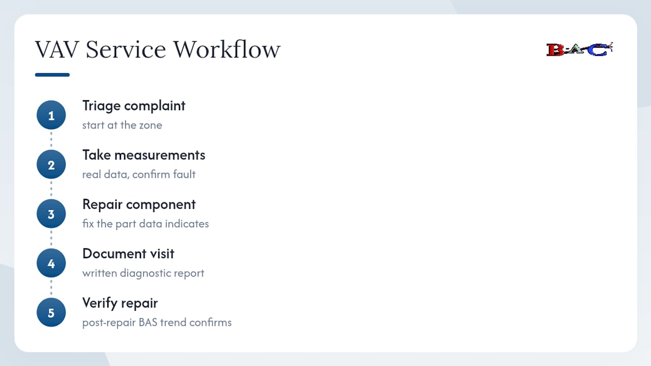
Most VAV complaints that reach us have already been “fixed” once, usually by someone who raised a setpoint or swapped a part without confirming what was actually broken. Our process starts at the zone and moves upstream in the same order this guide follows: triage the complaint, take real measurements, then repair the specific component the data points to.
Since 1993, our technicians have carried that discipline into commercial buildings across every VAV configuration you’ll find in a New Jersey office park or industrial facility. Every service visit leaves the customer with a written diagnostic report, the specific repair performed, and a post-repair BAS trend showing the fix actually held. That last step matters more than most people expect. A controller can report success while the diffuser still runs warm, and the only way to catch that gap is to check both.
— John
Ready to Book a VAV Diagnostic Visit?
If you’ve run the checks above and the box is still warm, the fault is likely one that needs hands-on repair rather than another round of testing: a burned-out actuator, a stuck reheat valve, a BAS reprogramming issue, or an AHU that isn’t hitting its supply-temperature setpoint. That’s where Brighton Air Corp earns its keep. Our commercial technicians carry the manometers, pitot gauges, and BAS access to finish in one visit what a partial field check leaves half diagnosed, backed by 24/7 emergency response when a warm zone can’t wait for a scheduled slot.

When you request service, give us the zone name or room number, how long the complaint has been going on, and, if you have BAS access, a trend snippet covering the last few hours of cooling calls. Tell us your preferred access window too, especially for occupied commercial space where timing matters. Request a service visit through Brighton Air Corp and get a technician who diagnoses before they touch a wrench.
Sources
Four sources are worth bookmarking for ongoing VAV work. Johnson Controls’ VMA troubleshooting bulletins walk through PID saturation and Starved Box logic in detail. PNNL’s VAV operations and maintenance guidance covers system-level checks that separate terminal faults from central plant issues. Price Industries’ supply-air temperature guidance sets the diffuser temperature benchmarks used throughout this guide. And EnergyStar’s building upgrade manual frames the documentation habits that make repeat troubleshooting faster.