
How Explosion-Proof HVAC Systems Work: A Facility Manager's Guide
How Explosion-Proof HVAC Systems Work: A Facility Manager’s Guide
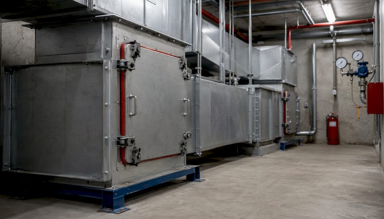
Explosion-proof HVAC systems are specifically engineered to operate safely in hazardous (classified) locations where flammable gases, combustible dusts, or ignitable fibers are present. Under NEC Article 500, any facility with a classified location must use equipment specifically identified for the class and explosive properties present. The ASHRAE Guide for HVAC in Hazardous Spaces adds that designers typically need a combination of protection strategies rather than a single fix. Three primary approaches cover most applications:
- Containment (Ex d / flameproof): Enclosures strong enough to contain an internal ignition without propagating flame outward
- Prevention (Ex i / intrinsically safe): Control circuits limited to energy levels too low to ignite a hazardous atmosphere
- Encapsulation (Ex m): Motors and circuit boards potted in insulating compound, isolating components from oxygen and moisture
If your facility handles petroleum vapors, grain dust, or textile fibers in any process area, NEC Article 500 almost certainly applies. Brightonaircorp works with industrial clients across New Jersey to navigate exactly this compliance path.
Key Takeaways
Explosion-proof HVAC systems require the right combination of containment, prevention, and operational controls — specified to the NEC area classification, approved by the AHJ, and verified through functional commissioning before handover.
| Point | Details |
|---|---|
| NEC Article 500 is the trigger | Area classification determines required equipment class, group, and temperature code before any design begins. |
| Three protection techniques | Ex d containment, Ex i intrinsic safety, and Ex m encapsulation each serve different power levels and use cases. |
| AHJ approval is mandatory | Submit classification drawings, equipment listings, and purge documentation before installation; plan four to eight weeks for review. |
| Commissioning must be functional | Purge interlock, pressure hold, and sensor failover tests must be completed and recorded before handover. |
| Brightonaircorp covers the full scope | From risk analysis and specification through installation, commissioning, and maintenance contracts across New Jersey. |
Table of Contents
- How explosion-proof HVAC systems prevent ignition and contain internal events
- When code requires explosion-proof HVAC: NEC Article 500 and the AHJ
- Design process: choosing protection techniques and filtration
- Installation and code best practices every contractor must follow
- Commissioning, testing, and maintenance for reliable operation
- Costs, tradeoffs, and the business case for explosion-proof HVAC
- Common mistakes and red flags to watch for
- Brightonaircorp’s practical perspective on what actually matters
- Brightonaircorp handles classified-location HVAC from spec to sign-off
- Authoritative resources and standards
- Sources
How explosion-proof HVAC systems prevent ignition and contain internal events
Three mechanisms define how these systems function: physical containment of any internal ignition, prevention of ignition through energy limitation, and operational controls that keep hazardous concentrations below ignitable thresholds.
Flameproof enclosures (Ex d) are built to withstand an internal explosion and cool escaping gases through precision-machined flame paths before they reach the external atmosphere. The enclosure does not prevent ignition inside; it stops that ignition from becoming an external event. UL standards describe this containment-versus-prevention distinction as fundamental to equipment selection.
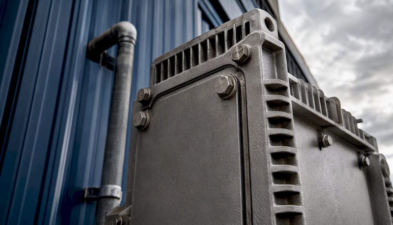
Intrinsically safe circuits (Ex i) take the opposite approach. Per Fluke’s technical comparison, intrinsically safe equipment limits available energy so that no spark or thermal event can ignite the surrounding atmosphere, regardless of a fault condition. This makes Ex i ideal for sensors, transmitters, and low-power control wiring.
Encapsulated motors and boards (Ex m) use specialized insulating compounds to pot circuit boards and windings, physically isolating components from oxygen and moisture, similar to the advantages described in blown-in insulation for homeowners which enhances protection and efficiency. IEC guidance documents this as a standard construction practice for hazardous-area electronics.
Operationally, ASHRAE outlines three controls that work alongside the hardware:
- Initial purge: Before startup, the system flushes the conditioned space and equipment internals to reduce combustible concentration below the lower explosive limit.
- Positive pressurization: Maintained differential pressure prevents hazardous vapors from infiltrating equipment enclosures or conditioned spaces.
- Temperature and humidity control: Keeping conditions within defined bands reduces condensation (which can carry corrosives) and limits thermal ignition risk.
| Protection Technique | How it prevents ignition | Best use case | Installation complexity |
|---|---|---|---|
| Ex d (flameproof enclosure) | Contains internal event; cools escaping gases | Motors, junction boxes, large drives | High — precision machining, thread engagement |
| Ex i (intrinsically safe) | Limits circuit energy below ignition threshold | Sensors, transmitters, control loops | Moderate — requires certified barriers |
| Ex m (encapsulation) | Isolates components from atmosphere | PCBs, small motors, sealed assemblies | Low to moderate — factory-applied |
| Purge and pressurization | Dilutes/removes hazardous atmosphere | Entire enclosures or rooms | Moderate — requires pressure monitoring |
Key design insight: Pressure sensors and purge vents should never be located on the same wall face as process exhaust vents. Placing them there creates a flow path that draws hazardous vapors directly into equipment during the purge cycle — the opposite of the intended effect. Site sensors on the clean-air side and vent purge exhaust away from process sources.
Pro Tip: Specify a time-delay interlock that prevents the HVAC system from energizing until the purge cycle completes and pressure sensors confirm the enclosure has held positive pressure for the required dwell time. This single control interlock eliminates the most common startup-sequence failure.
When code requires explosion-proof HVAC: NEC Article 500 and the AHJ
NEC Article 500 is the governing trigger. It defines three classes of hazardous locations based on the type of hazardous material present, and Articles 500–503 map each class to specific equipment requirements.
| NEC Class | Hazardous material | Typical facility examples | HVAC implication |
|---|---|---|---|
| Class I | Flammable gases or vapors | Refineries, paint booths, chemical plants | Ex d or Ex i equipment; purge/pressurization |
| Class II | Combustible dusts | Grain elevators, flour mills, battery plants | Dust-tight enclosures; sealed conduit |
| Class III | Ignitable fibers or flyings | Textile mills, sawmills, cotton gins | Non-sparking components; filtered intakes |
Each class is further divided into Division 1 (hazard present under normal operating conditions) and Division 2 (hazard present only under abnormal conditions), or the IEC Zone system (Zones 0/1/2 for gases; Zones 20/21/22 for dusts). Division/Zone determines how stringent the equipment protection level must be.
Area classification is a team responsibility. Per EC&M’s guidance on classified locations, the owner’s representative, electrical engineer, process engineer, and fire protection engineer typically collaborate to produce the classification drawing and report. That documentation goes to the Authority Having Jurisdiction (AHJ) for approval before installation begins.
What the AHJ typically requires:
- Completed area classification drawing with Division/Zone boundaries
- Equipment listing certificates (UL, FM, or equivalent third-party)
- Design drawings showing conduit routing, sealing locations, and grounding
- Written purge sequence and pressure setpoint documentation
Timeline reality: AHJ review cycles vary by jurisdiction, but plan for four to eight weeks for initial approval on a new classified installation. Submit documentation early.
Design process: choosing protection techniques and filtration
Good explosion-proof HVAC design starts with a holistic risk analysis, not a catalog selection. Before specifying a single component, the design team must identify every hazardous substance present, its likely concentration range, process cycle timing, and how ventilation paths interact with process equipment.
The ASHRAE guide is explicit: designers may need combined protection methods and integrated chemical filtration when toxic or corrosive substances are present alongside flammable ones. A paint spray booth, for example, may need Ex d motors and activated-carbon filtration to prevent solvent vapors from recirculating through the air handler.
Choosing the right protection technique:
- Use Ex i for low-power instrumentation and control wiring where portability or frequent access is needed.
- Use Ex d for motors, drives, and junction boxes where higher power levels make energy limitation impractical.
- Use non-incendive components (Division 2 / Zone 2 only) where the hazard is present only under abnormal conditions and cost is a constraint.
Minimum spec deliverables every vendor proposal should include:
- Equipment class/group/temperature code ratings matching the area classification
- Third-party listing marks (UL, FM, CSA, or ATEX for imported equipment)
- Documented purge sequence with timing and pressure setpoints
- Filtration specification: HEPA, activated carbon, or chemical scrubbing stage as required
- Maintenance intervals for filters, sensors, and enclosure inspections
Pro Tip: Request the vendor’s HVAC lifecycle cost analysis alongside the equipment quote. Purge systems consume energy continuously; a proposal without purge energy consumption data is an incomplete bid.
Installation and code best practices every contractor must follow
The most critical installation requirements under NEC are threaded conduit engagement, raceway sealing, grounding and bonding, and equipment labeling. Get any one of these wrong and the system’s explosionproof integrity is compromised regardless of how well the equipment was specified.
EC&M’s NEC hazardous-location guidance specifies that threaded conduit entries must be made wrenchtight with at least five threads engaged. The reason is mechanical: expanding gases from an internal ignition must travel through enough thread length to cool below the ignition temperature of the external atmosphere before escaping.
NEC rationale: Threaded conduit entries are not just a mechanical connection. The thread path is a designed flame barrier. Insufficient engagement means gases exit hot enough to ignite the surrounding atmosphere, defeating the entire containment strategy.
Acceptance inspection checklist — require these from every contractor at handover:
- Equipment listing certificates on file for every classified-location component
- Conduit seals installed within 18 inches of every enclosure entry (per NEC Sec. 501.15)
- Thread engagement verified and documented (wrench-tight, minimum five threads)
- Grounding and bonding continuity tested and recorded
- Intake and exhaust locations confirmed away from process vents and loading areas
- AHJ sign-off on area classification drawing and equipment schedule
Intake placement deserves specific attention. A plenum design that pulls make-up air from a location upwind of process exhausts avoids recirculating hazardous vapors into the conditioned space. Never site an intake within 10 feet of a process vent, relief valve, or drum-filling station without a dispersion analysis.
Commissioning, testing, and maintenance for reliable operation
Commissioning must validate purge timing, pressure setpoints, sensor calibration, and enclosure integrity before the system is handed over. A system that passes a visual inspection but has never had its purge interlock functionally tested is not commissioned — it is installed.
Commissioning checklist:
- Functional purge test: confirm purge cycle runs to completion and interlock prevents startup if pressure is not achieved
- Pressure hold test: seal enclosure, apply rated pressure, confirm no decay over the specified dwell time
- Sensor failover test: simulate sensor failure; confirm system de-energizes or alarms per design intent
- Control interlock verification: confirm all interlocks (purge complete, pressure maintained, temperature in range) are wired and functional
- Leak test: pressurize conduit and enclosure system; check for leaks at seals, fittings, and cable entries
- Certification verification: confirm all listing certificates match installed equipment serial numbers
Ongoing maintenance schedule:
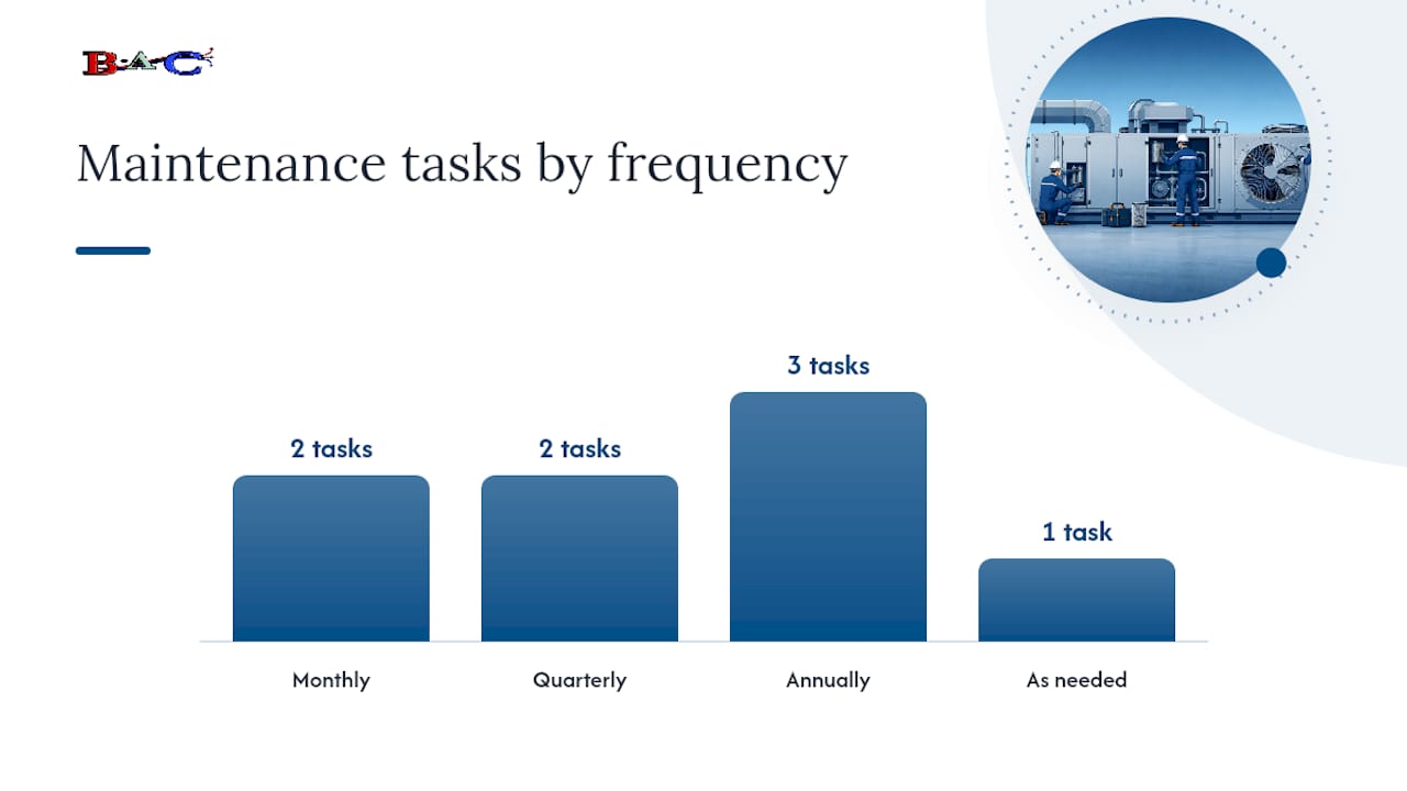
- Monthly: Check differential pressure readings and log trends; inspect filter condition
- Quarterly: Recalibrate pressure and temperature sensors; inspect enclosure gaskets and flame paths
- Annually: Motor insulation resistance test; full purge sequence functional test; torque check on all threaded conduit entries
- As needed: Filter replacement per manufacturer schedule or when pressure drop exceeds setpoint
Pro Tip: Keep a pressure-decay trending log rather than just a pass/fail record. A slow upward trend in decay rate over six months is an early warning of gasket degradation or a loose threaded entry — caught early, it is a $50 gasket replacement. Missed, it is a compliance failure at the next AHJ inspection.
Commissioning records must be retained and made available for AHJ inspections. A warehouse HVAC management approach that includes documented service logs translates directly to classified-location compliance.
Costs, tradeoffs, and the business case for explosion-proof HVAC
Explosion-proof systems cost more upfront. Specialized enclosures, certified motors, purge controls, third-party listings, and AHJ documentation all add to capital expenditure compared to a standard commercial system. The business case rests on what the alternative actually costs.
Primary cost drivers:
- Ex d enclosures and certified motors (typically a significant premium over standard equipment)
- Purge and pressurization controls with redundant pressure monitoring
- Chemical filtration stages for corrosive or toxic environments
- Third-party certification and listing fees
- AHJ documentation, inspections, and potential re-inspection cycles
The ROI argument is straightforward. A single unplanned shutdown in a chemical plant or grain-processing facility can cost far more than the entire HVAC system. OSHA citations for noncompliant electrical equipment in classified locations carry per-violation penalties, and liability exposure from an incident in an unprotected classified area dwarfs any capital savings from under-specifying the system.
Ask vendors for life-cycle cost data that includes purge energy consumption, filter replacement frequency, and projected sensor recalibration costs. A lower-bid system with high purge energy draw may cost more over a ten-year horizon than a higher-efficiency design. HVAC lifecycle cost analysis frameworks apply directly here.
Common mistakes and red flags to watch for
The most dangerous assumption in classified-location HVAC is that “explosion-proof” means the system is indestructible or that one protection technique covers every risk. It does not.
Critical misconception: “Explosion-proof” describes a containment strategy for an internal ignition event. It says nothing about whether the system prevents product contamination, handles corrosive recirculation, or protects against a fire originating outside the enclosure. A system can be fully NEC-compliant and still fail to address the actual hazard profile of a specific facility.
Inspection red flags:
- Missing or illegible equipment markings (class, group, temperature code)
- No area classification drawing on file or AHJ approval documentation absent
- Threaded conduit entries not wrenchtight or with fewer than five threads engaged
- Conduit seals missing or improperly filled
- Purge sequence not documented or interlock bypassed
- Mixed protection strategies without engineering justification (e.g., Ex i sensors wired into a non-certified barrier)
The most serious consequence of any of these gaps: uncertified equipment or missing AHJ approval can trigger an immediate stop-work order, force a full re-inspection, and create direct legal liability if an incident occurs. Per NEC Sec. 500.8(B)(1), equipment used in classified locations must be specifically identified for the class and explosive properties present. “Close enough” is not a recognized equipment rating.
Brightonaircorp’s practical perspective on what actually matters
The technical standards are clear. What gets facilities into trouble is not ignorance of NEC Article 500 — it is the gap between what a proposal says and what gets installed. Brightonaircorp’s recommendation for every classified-location project starts with a documented risk analysis, third-party listed equipment, and a commissioning plan that requires functional testing before handover, not just a visual sign-off.
Specific checks Brightonaircorp insists on in every proposal review:
- NEC/UL listing certificates matched to the area classification drawing
- Purge sequence documented with timing, pressure setpoints, and interlock logic
- Pressure monitoring specified with redundant sensors and alarm outputs
- Maintenance plan included with filter intervals, sensor recalibration schedule, and annual functional test requirements
- Contractor references from at least two comparable classified-location installations
Pro Tip: Request a field acceptance test with the AHJ present before final payment. Contractors who resist this condition are telling you something about their confidence in the installation.
The perspective here is grounded in what the standards require and what audits actually find. Facilities that treat commissioning records as a compliance formality rather than a living document are the ones that fail AHJ re-inspections.
Brightonaircorp handles classified-location HVAC from spec to sign-off
Specifying and installing explosion-proof HVAC correctly requires deep familiarity with NEC Article 500, ASHRAE design guidance, and the AHJ approval process. Brightonaircorp brings that expertise to industrial and commercial facilities across New Jersey, covering every phase from initial site risk analysis through turnkey installation and ongoing maintenance contracts.

Services include area classification support, specification writing, UL and third-party equipment coordination, functional commissioning, and scheduled maintenance agreements. Facilities that engage Brightonaircorp early in the design phase avoid the costly re-work that comes from AHJ rejections and equipment substitutions mid-project. Check AHJ-specific requirements before finalizing your design drawings — jurisdiction review timelines vary and can affect your project schedule significantly.
Contact Brightonaircorp for a site risk analysis and design consultation. The earlier in the project, the better.
Authoritative resources and standards
Key standards and guides every facility team and designer should have on hand:
- NFPA 70 (NEC), Article 500: The primary U.S. code governing hazardous (classified) locations, equipment selection, and installation methods. Required reading for any classified-location project.
- ASHRAE — Hazardous Space HVAC Guidance: Design steps for identifying hazardous substances, selecting protection methods, and specifying filtration. Covers hybrid protection strategies and documentation best practices.
- UL Standards and Listings: Equipment testing and marking expectations for explosion-proof and intrinsically safe components. Use UL’s online certifications directory to verify listed equipment before acceptance.
- IEC Standards: International framework for Ex protection techniques including Ex d, Ex i, Ex m, and encapsulation practices. Relevant for imported equipment and ATEX-marked components.
- EC&M — NEC Requirements for Hazardous Locations: Practical code commentary on thread engagement, raceway sealing, and conduit installation requirements.
- EC&M — Classification of Hazardous Locations: Explains the design team’s role in area classification and the documentation required for AHJ acceptance.
- Fluke — Intrinsically Safe vs. Explosion-Proof: Clear technical comparison of containment versus prevention strategies; useful for cross-discipline teams explaining the distinction to non-electrical stakeholders.
- Up.codes — Classes I, II, and III: Searchable NEC code text mapping each class to hazard types and equipment requirements across Articles 500–503.
Sources
- NFPA 70 (NEC) — NFPA
- ASHRAE — American Society of Heating, Refrigerating and Air-Conditioning Engineers
- UL standards and guidance — UL
- Intrinsically safe vs. explosion-proof — Fluke
- International Electrotechnical Commission (IEC)
- Up